These notes are intended for personal use only, if you are painting a model for yourself then feel free to use them. If you wish to use these notes for commercial purposes then contact me first. The latest additions and amendments are shown in red.
GREAT WESTERN RAILWAY
LOCOMOTIVE LIVERIES 1923 – 1939 (revised 12.11.23)
INTRODUCTION
The story of the GWR’s liveries is more simple than the other grouped railways in that, at the Grouping, in 1922-23, it simply carried on as before, but with the addition of stock from the absorbed railways. The other railways, and indeed British Railways later, had to fit a standard lined livery to the many and varied fleet they took over, but the GWR did not treat any of the absorbed stock to a lined livery. From 1923 only six classes of engine received lining, and given the standardisation and strong family resemblance within the group, I am surprised that there is not a definitive work available which would enable one to paint a model properly.
The LMS, with all its complexities, is well covered by ‘Locomotives of the LMS’ in five volumes by Essery & Jenkinson. The LNER too is well covered, with the hallowed green books from the RCTS and of course the excellent Yeadon series. The Southern less so, with only the HMRS Livery Register No. 3 to go on. My own copy is well annotated with crossings out, question marks and the occasional ‘no!’
The only attempts to codify the GWR livery
are the
I can see that I am digging a hole for myself here. I do not claim that my livery details are the ultimate definitive answer but, if it allows me to paint a model without further references, apart from a reasonable photograph, then it will have done its job. There are still some gaps so if any one can add information, or dispute it, then use the Contact Us button to send the information. Your contribution will be acknowledged if you wish. Wikipedia this is not, but hopefully a decent register can be built up.
My thanks to Bob Meanley, CME at Tyseley Works, for much of the detail relating to GWR liveries.
--------------------------------------------
COLOURS
The question of colour is a difficult one, as can be seen on numerous preserved GW locomotives all in different hues and shades. The colours I describe are for a model. There was an alleged change to the green in 1928 - I cannot say if this is true, as I have yet to see evidence.
Main colours
1 Middle Chrome Green. This is the principal body colour. I, and most professional painters, advocate Land Rover Deep Bronze Green. It is alleged that the preserved Caerphilly Castle, albeit painted by BR, carries a true Great Western green. The colour is not, and never has been, 'Brunswick Green'. Never ever, under any circumstance, use a photograph to match a colour.
2 Black. The GWR used different types of black paint on different parts of the engine and tender, for example, oil paint, oil paint mixed with varnish, smoke stack black and bituminous black. For a model any black, except matt, will do.
Secondary colours
3 China or Chinese Red for buffer plates and cases.
4 Venetian Red for various surfaces inside the main frames between smokebox and firebox. Venetian Red is Red Oxide by another name.
5 Pale Yellow for the painted numbers and rim of cast iron number plates.
Lining colours
6 Chrome Orange. This is just on the yellow side of pure orange. A thin line of chrome orange against the green of a model looks too yellow so I use Humbrol Tan (No. 9) with a bit of red mixed in.
2 Black. Any gloss will do so long as it has plenty of body.
------------------------------------------------
LIVERY STYLES
Style A - Stars, Saints, Castles, Kings & Halls.
Mid Chrome Green generally above the running plate and generally Black below. Lining applied in various styles to Green areas - cab sides, tender sides and rear, splashers, boiler bands, weatherboard, firebox, name plate support plates, and rear edge of cab interior. Lining on Black areas included hanging bars, step plates, brake hangers, tender frames, King Class bogie frames and front stretcher, and number plates. Buffer plates and cases were also lined. The detail is given in a later section.
Style B – All other engines except below.
Mid Chrome Green generally above the running plate and generally Black below. No lining. Detail given in a later section.
Style C – Some of the acquired ROD 2-8-0s that were usable but expected to be withdrawn before a major overhaul. Some other absorbed engines also fell into this category but I have no examples..
Black all over except buffer plates and cases, and inside face of frames etc as Styles A & B.
-----------------------------------------------------
LINING STYLES
Lining Rule 1 – Where possible the Orange line does not run over rivets.
Lining Rule 2 – Lining dimensions can be adjusted to comply with rule 1.
As some lining styles are applied to different background colours I have used the abbreviation BGC where a particular style can applied to more than one colour.
Style 1 - On larger panels, inset from the edge – cab sides, tender sides and rear, - and on boiler bands.
⅛” Orange / ½” Green / 1” Black / ½” Green / ⅛” Orange. Corner radius 3” to outside of outer Orange line except lower front corner of cab lining and adjacent to cab cut out. The boiler bands on the flat top of the firebox were not lined.
Style 2 - Edge lining on smaller panels – splasher faces (except where style 2S applies), weatherboard, rear edge inside cab, fire box sides over splashers, and buffer plates.
½” Black / ½” BGC / ⅛” Orange. (Note this is style 1 split in half)
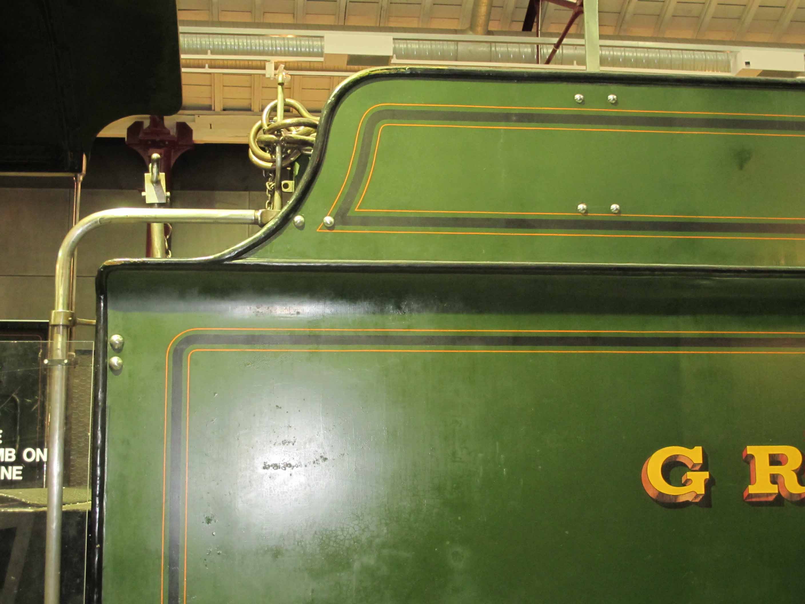
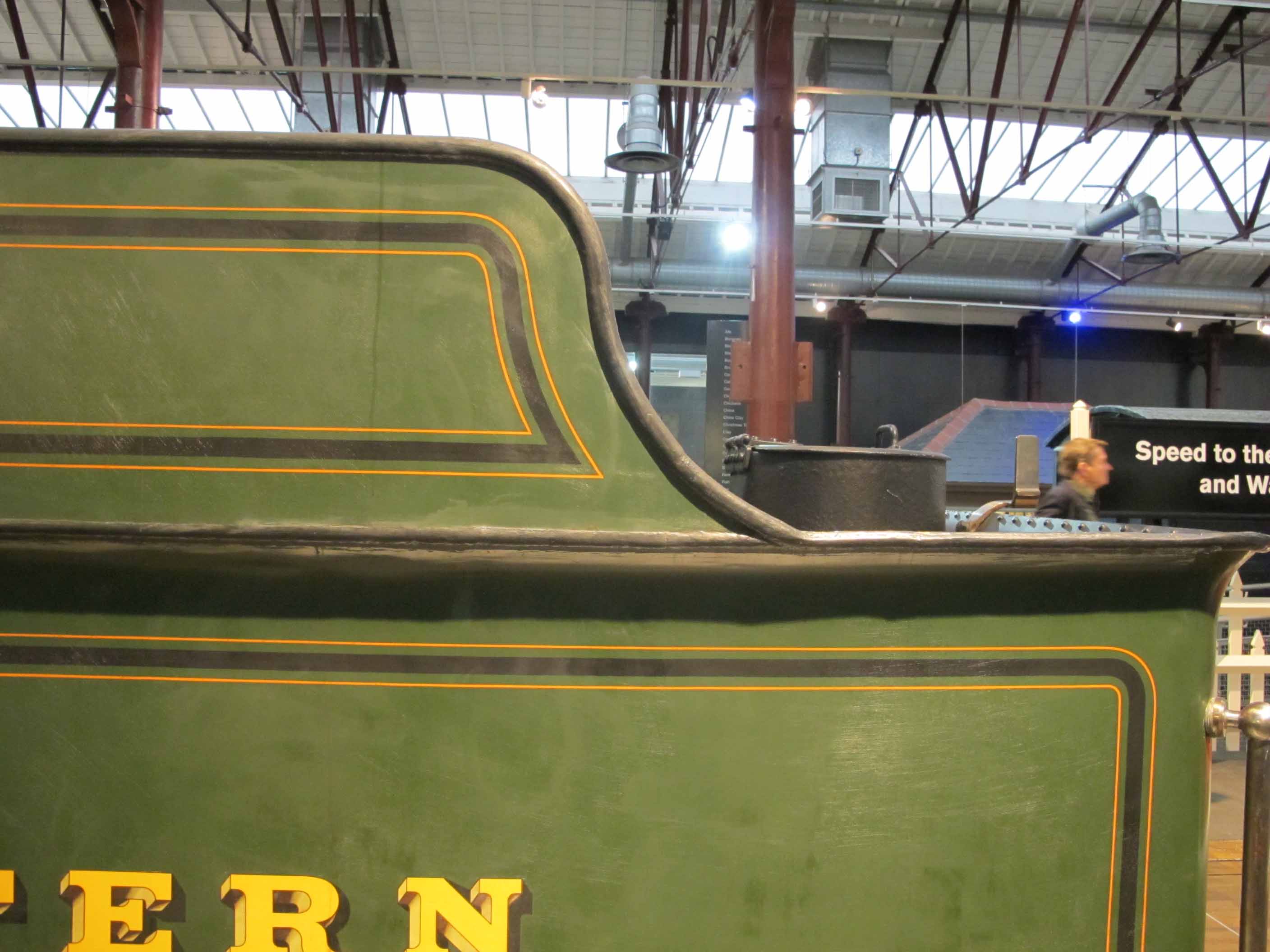
On weatherboards there were areas where there was no room for the Orange line so, while the Black line continued along the relevant edge, the Orange line joined an adjacent lining set. See photo A1, A2, A8 & A9
Style 2S - Edge lining on smaller panels - only on splashers on Stars and Saints without brass beading but with an arc of rivets, in order to comply with Lining Rule 1.
1½” Black / ½” Green / ⅛” Orange
Style 3 - Edge lining in Orange only.
½” BGC / ⅛” Orange. Where this disappears or ‘scarfs’ into an edge the dimensions taper off to zero.
Style 4 - At junction between firebox and weatherboard.
⅛” Orange / ½” Green / 1” x 1” angle all Black / ½” Green / ⅛” Orange.
The Orange line was missed out over the top of the firebox.
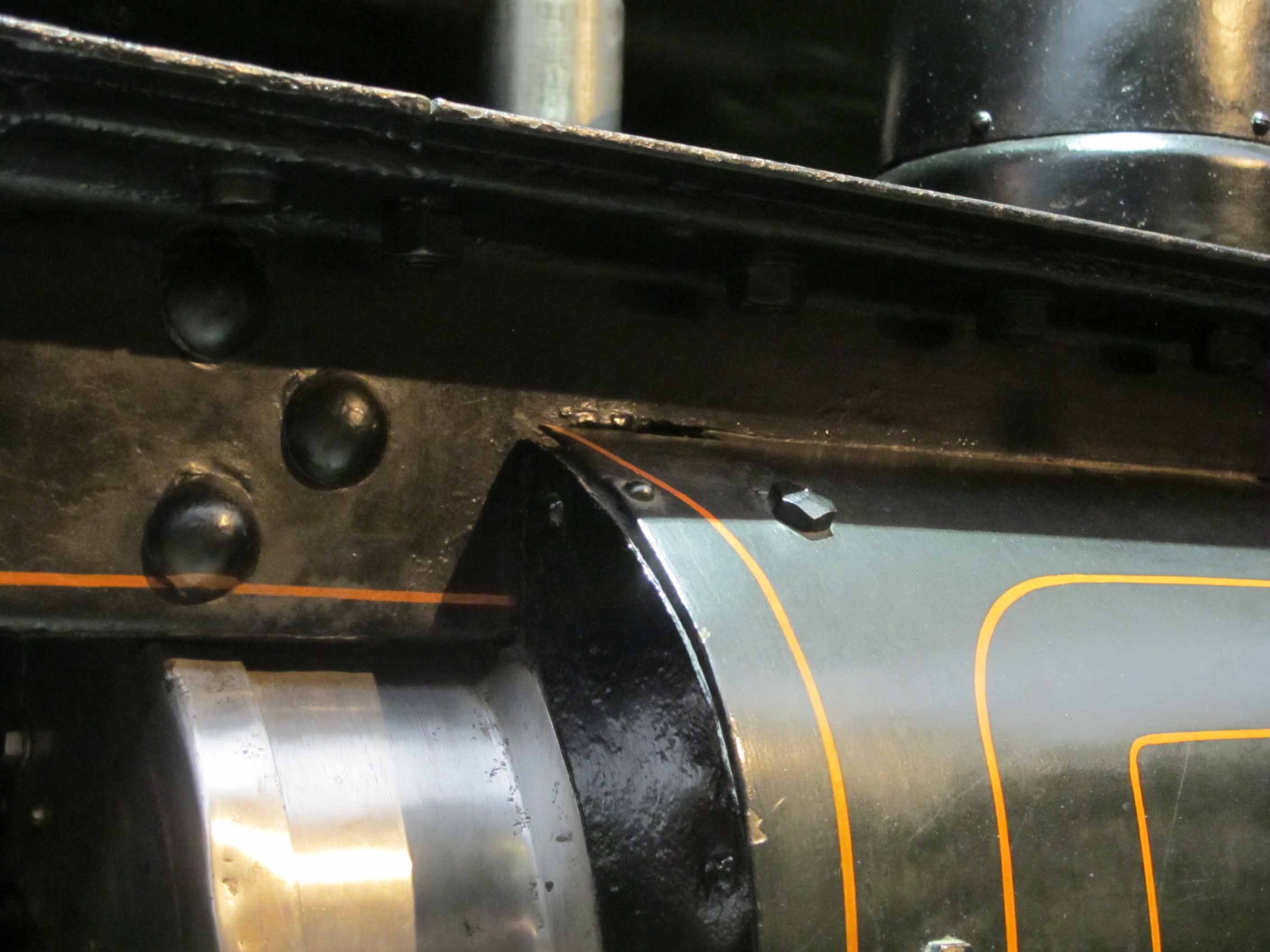
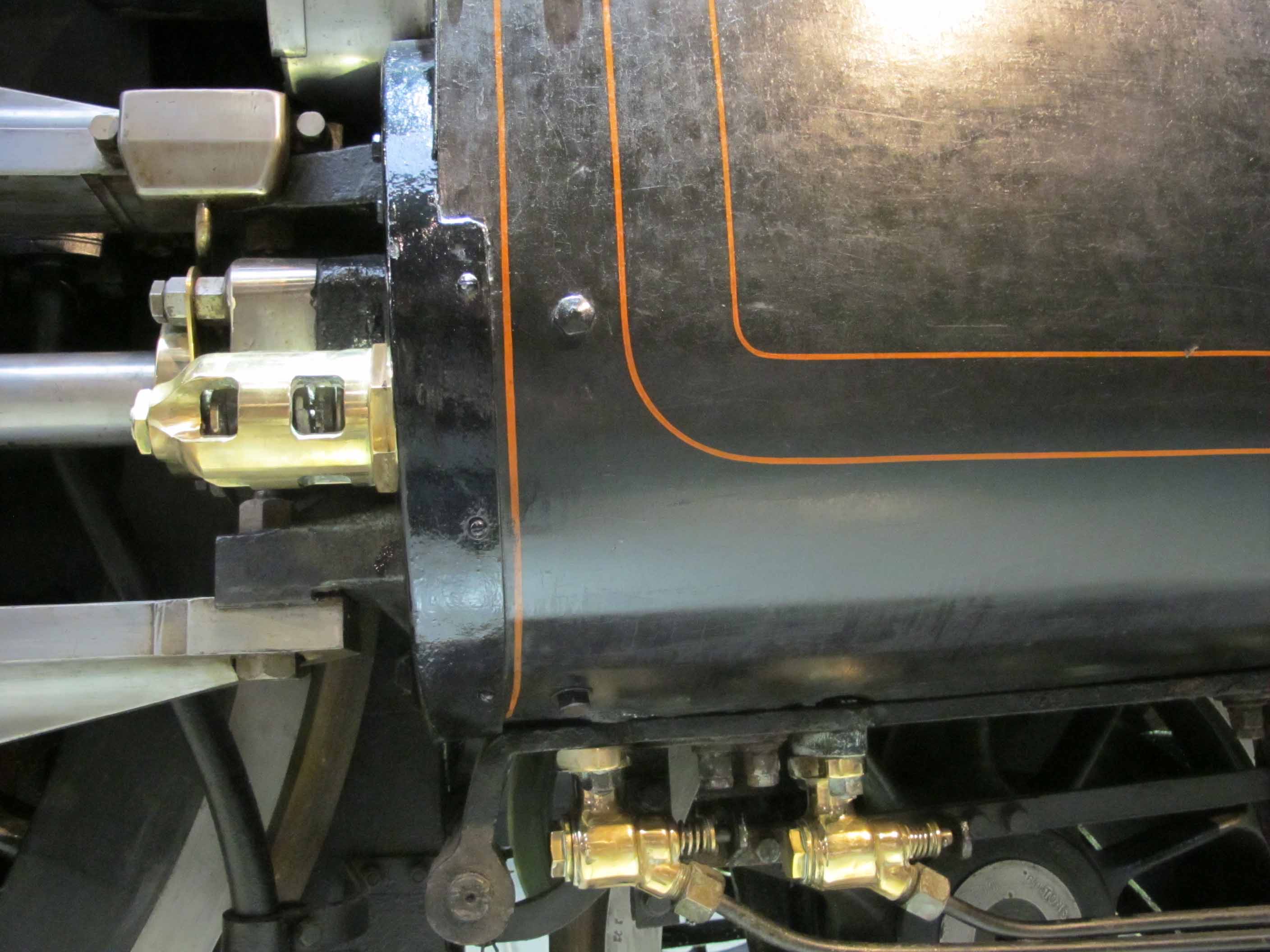
Style 5 - Cylinder lining.
The position of the lining did vary slightly depending on positions of rivets on the cylinder cladding and of course there was a difference between 2 cylinder and 4 cylinder engines. This is best described with reference to a photograph. See photos B7, B8 & B9.
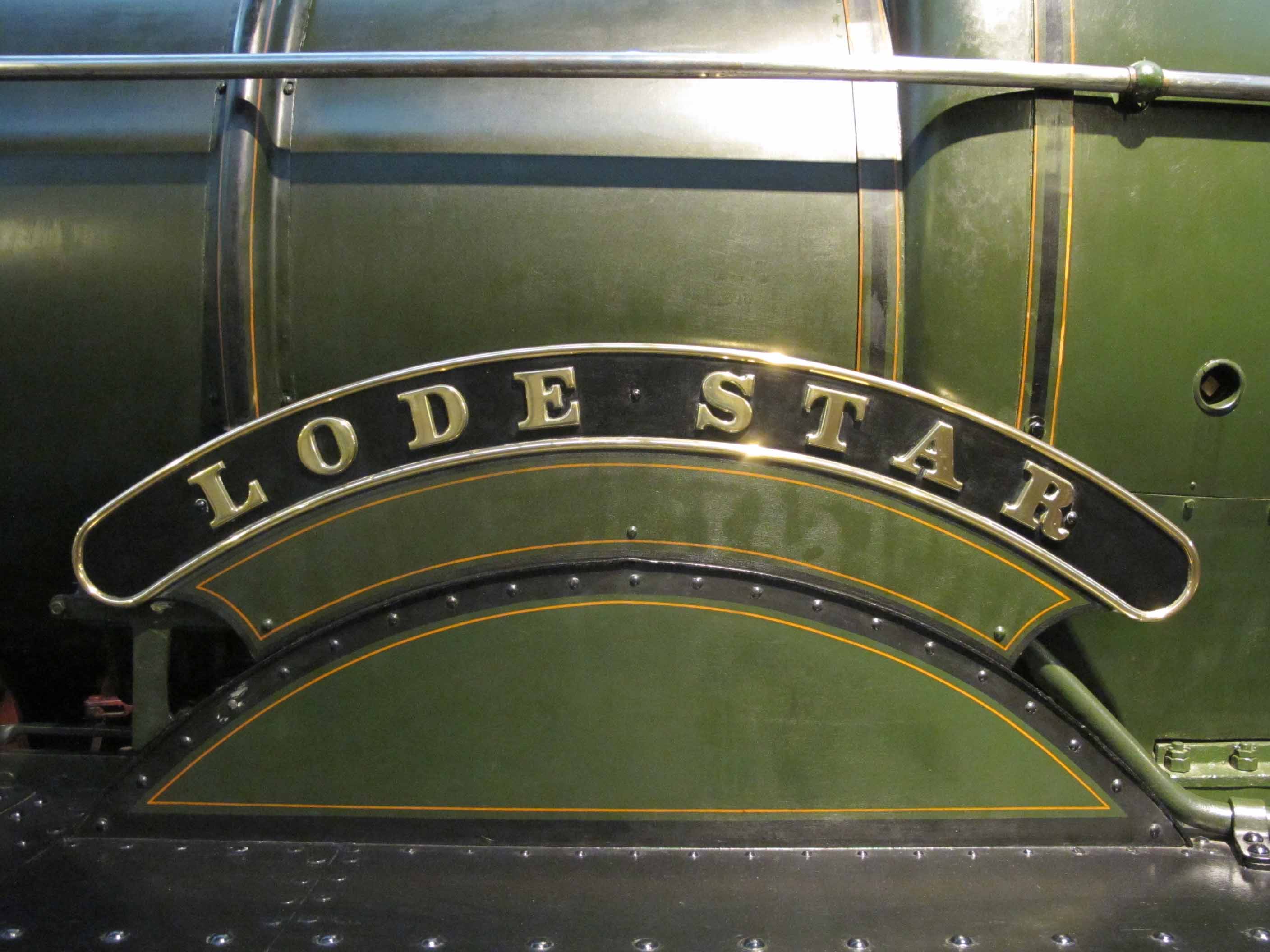
1” Black / ⅛” Orange. Adjacent to the front and back edges of the cylinder but curving in to the cylinder edge at the ends, the upper curve scarfing off towards the top corner of the cylinder cladding. (On Lode Star this lining is absent.)
And a panel with 2 1/2” corner radius and set 2” in from the edge lining.
⅛” Orange / 2” Black / ⅛” Orange.
-----------------------------------------------------
LIVERY STYLES A & B, Colour in detail
Black –
Running plate, hanging bars, drag beam, lamp brackets fitted to running plate and smoke box, outside face of frames and all springs & axle boxes etc attached, step plates, cross head, slide bars and C-bracket except for sliding surfaces, outside cylinders. Above the running plate the Black areas were smoke box and saddle, chimney, the front of pannier and saddle tanks where this was adjacent to the smokebox, cab roof, tops of side tanks, reverser rod, ejector pipework, tops of splashers*, pipe work attached to top of running plate, inside of bunker, inside, top and front of tender. On tank engines the front of the bunker within the cab. Pannier tank supports adjacent to smokebox.
Beading on the front and top edges of tenders and tanks and also the beading along the base of the coal plate, where it joins the flare, was painted Black. Also Black as were the horizontal parts of steps attached to Green and Red areas. Ends and back of buffer plates. Fire box front within cab.
Name and number plates
*I have recently acquired a photograph showing newly painted Collett Goods No. 2239 at Swindon Works. Unfortunately the photo is undated but the tender has the 1934 monogram. It clearly shows that the rear splasher top is green and also the buffer casing rims are black. Does this mean that the rear splasher top on 4300s and 4700s could be green. One for the pedants to mull over. More evidence needed.
Wolverhampton variants - The rim on the end of the buffer cases was Black on plain green engines. The outside rear of the cab of tank engines, above the coal space was probably Black. This possibly explains the information I was given by an ex-engineman, but further confirmation would be good.
Mid Chrome Green –
Boiler, firebox, splasher faces, sides and top of fire iron tunnels, and top of splashers adjacent thereto, side tanks, saddle tanks, sides and top of pannier tanks, front of tanks where they were adjacent to the boiler, weather boards, sides and rear of bunker, sides and rear of tender. On tenders the Green extended to include all of the angle irons at the base of the sides and rear. Operating rods for the sanders, injectors above the running plate, boiler saddles. Tool boxes on the top of tenders. Inside walls and roof of cab including the cladding to the sides of the fire box, and excepting the front of the bunker within the cab of tank engines. AWS equipment within cab including the bell. Rear vacuum stand pipe above the buffer plate.
Venetian Red –
Inside face and all stretchers and castings forming the main frames between smoke box and fire box, axles, all castings forming part of the motion eg balance weights, cranks and eccentrics. Eccentric rods. Regulator lever within cab except the handle. (No handles or controls within the cab were ever painted red)
China Red (also known as Chinese Red) –
Buffer plates and cases, all of the front vacuum stand pipe and the part of rear stand pipe where it crosses the buffer plate. Exceptions - the step on the top of the buffer housing which is Black and, for Livery Style A, the rim of the buffer cases which is also Black.
Unpainted areas –
Whistles, brass window frames, brass splasher beading, raised parts of brass number and name plates, wooden parts within cab – floor, control handles, seats. Brass control handles – regulator, reverser. Non-ferrous metal parts attached to the firebox front. The hand rails adjacent to the cab entrance on both engine and tender were unpainted except for about an inch at each end. Forged parts of the motion and valve gear, except eccentric rods. For Livery Style A only (but also some in Style B) - copper chimney top, and brass safety valve bonnet and cab beading.
Details -
Hand rails –
Hand rails were painted in the same colour as the panel they were mounted on. The main boiler hand rails were therefore Black adjacent to the smokebox and changed to Green adjacent to the boiler. On pannier tanks the change from Black to Green was at the front edge of the tank. Exceptions - When mounted adjacent to a Black ejector pipe the hand rail was Green, and at the cab entrance both engine and tender rails were unpainted steel.
Cab doors on tank engines -
There is a question of whether these were green or black. In most photos the doors are open so it is not possible to see. There are some works grey photos where the doors appear to be a darker shade, hence indicating black rather than green.
A small detail –
On the curved drop below the cab side on some tender engines there was a small step. The step tread itself was painted Black, the step support was Green, the portion of running plate below the step was Black but the portion above the step was Green.
-----------------------------------------------------
Livery Style A, lining in detail
Lining on Green areas
Cab sides –
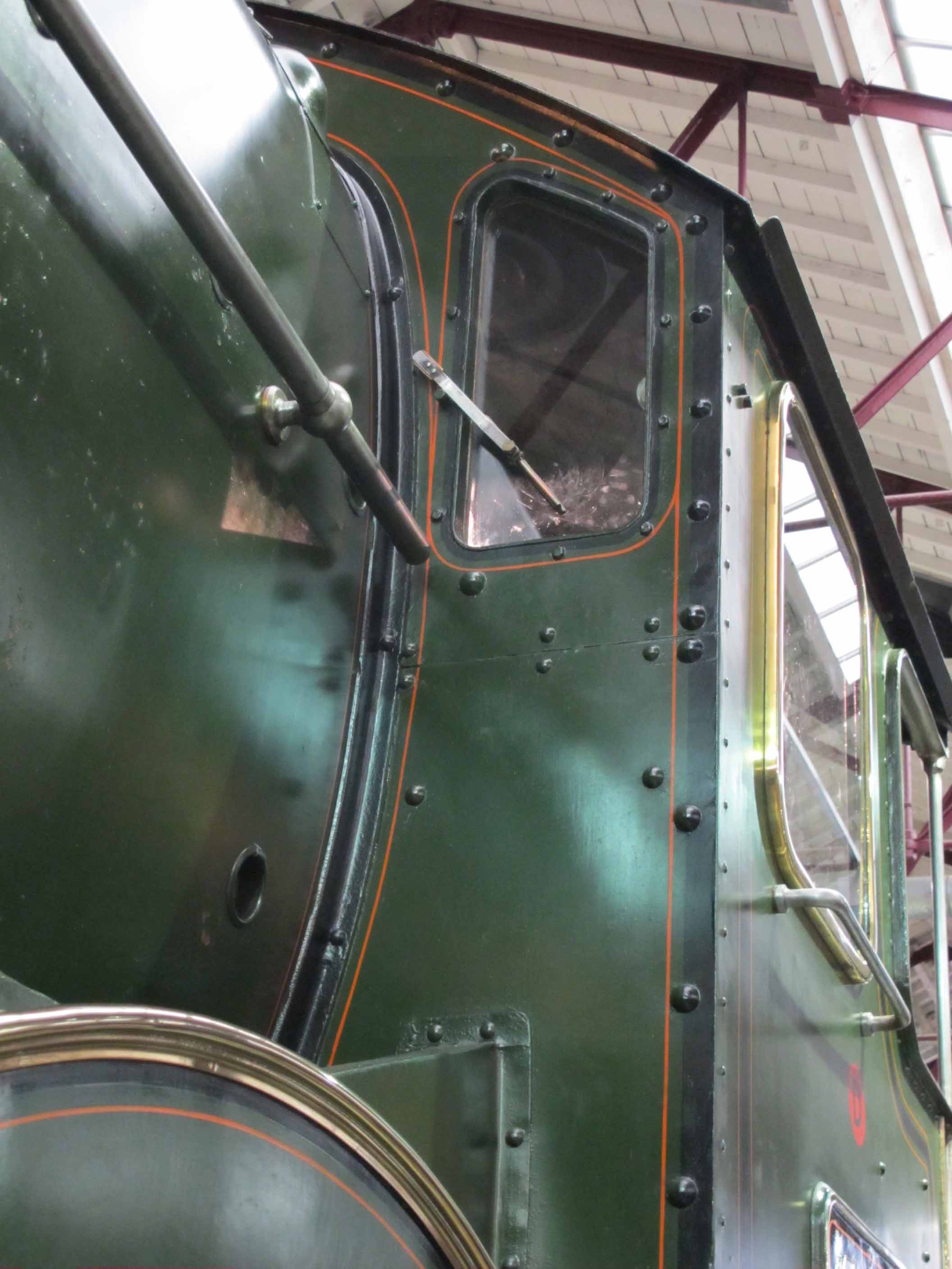
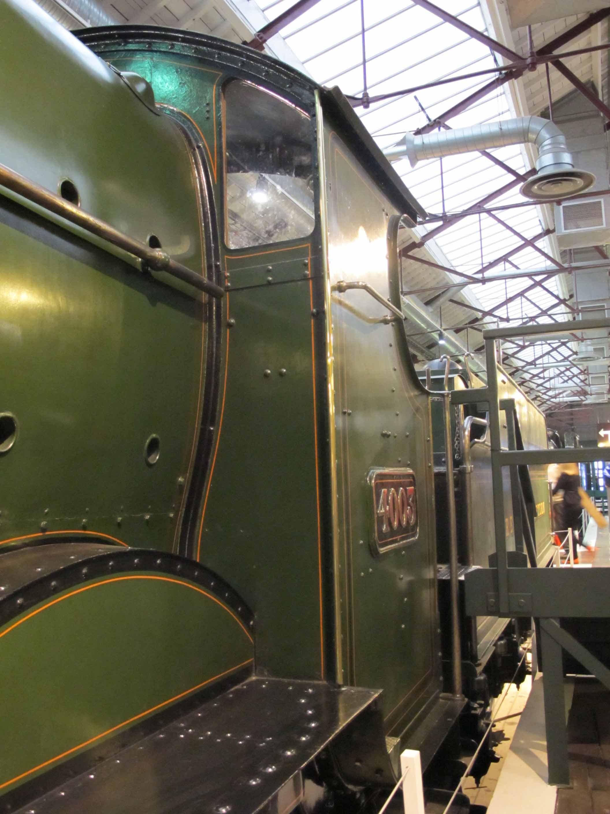
Lining Style 1 set in 3” from the edges. Top front and bottom rear corners were 3” radius to the outside of the Orange line. The radius at lower front and adjacent to the cut out were 3” plus/minus the radius of the edge. The top outer Orange line ran above the window frame on Castles, Kings and Halls but the black line was interrupted by it. The top rear corner formed an acute angle. In general the dimensions were adjusted to comply with Rule 1.
Collett tender sides –
Lining Style 1. The position of the lining was dictated by the position of the rivets in that the upper and lower Black line passed through the top and bottom rivets so that the lining was about 5 – 6” from the edge. The front vertical lining was immediately in front of the closely spaced rivets for the tender bulkhead. The Black line of the rear vertical lining ran through rivets to give a spacing of about 5” from the end. All corners were 3” radius.
Churchward tender sides –
Lining style 1. On a riveted tender the position of the lining was dictated by the rivets except that the lining tended to go between the rivets rather than the Black line being centred on them. The lower line was about 3” above the angle running along the base, and the top line was just below the dense line of rivets fixing the tank top to the sides. On these smaller tenders the coal plate itself was lined in Style 1 set in 3” from the edge. The bottom corners of the lining formed an acute angle. See photo A11 & A12
Tender back –
Lining Style 1. The horizontal lining ran at the same level as that on the sides. The vertical lining ran 5” in from the edge. All outer corners were 3” radius.
Splasher faces –
Castles, Kings, Halls and Stars & Saints with brass beading. Lining Style 2 along the base and along the top arc with the Black line adjacent to the beading. Both lines formed an acute angle at the bottom corners. See photo D1. Where a splasher was obscured by the weatherboard, or the reversing gear cover on the right hand side, the lining was deemed to continue behind, and was not ‘closed off’. See photo A7
Stars and Saints without beading and without an arc of rivets. The Black line of Lining Style 2 ran along the top edge of the splasher.
Stars and Saints without beading but with an arc of rivets. Lining Style 2S along the top so that the broad Black line covered the rivets. Lining Style 2S also along the base. See photos A4, A7 & A9.
Name plate support –
Lining Style 2 on all edges. See photo D1
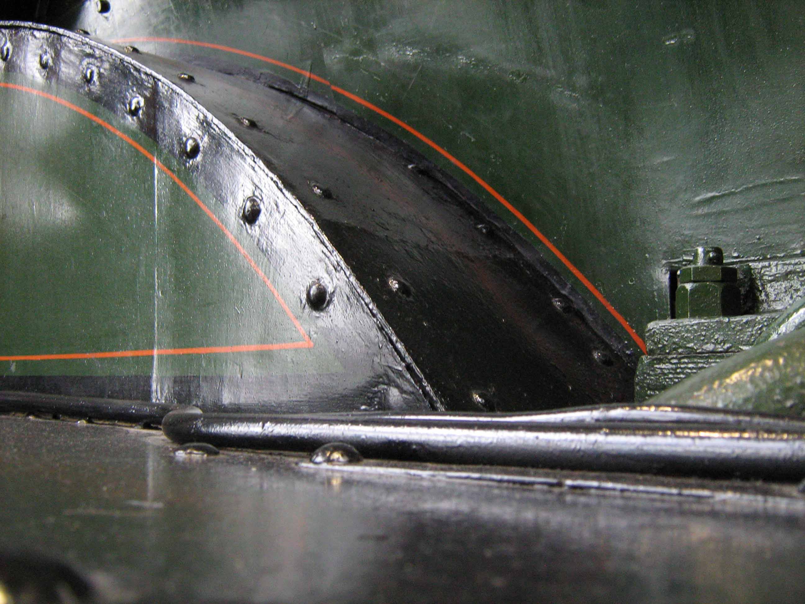
Weatherboard and fire box sides –
These can be treated as one entity, as the cab/firebox angle lining was common to both. The weatherboard was lined on the outer edges and spectacle frames in Lining Style 2. Where the angle iron joining the weatherboard to the cab side sheets and roof was on the face of the weatherboard it was painted Green and the lining put inside it. Where the angle was inside the cab the black edge line followed the outer edge of the weatherboard, the lining was deemed to go behind the reversing gear cover on the right hand side (Collett locos) and was not closed off. See photo A2.
Adjacent to the firebox the lining was in Style 4. This style continued for the length of the cab angle, (interrupted again by the cover box). The other half of Lining Style 4 lay on the fire box sides where at the lower edge it joined the lining above the splashers in Style 2. See photo A7. On engines with a fire iron tunnel on the left hand side there was no lining over the splashers. Where a portion of the centre driver splashers was adjacent to the fire box there was further lining over that part. See photo A5. There was no lining adjacent to the angle iron at the foot of the fire box cladding at running plate level. The lining on the weatherboard did not continue along the base parallel to the running plate (according to works grey photos and the two preserved engines painted at Swindon, but in earlier times the base was lined and also the lining hopped up over the splasher end).
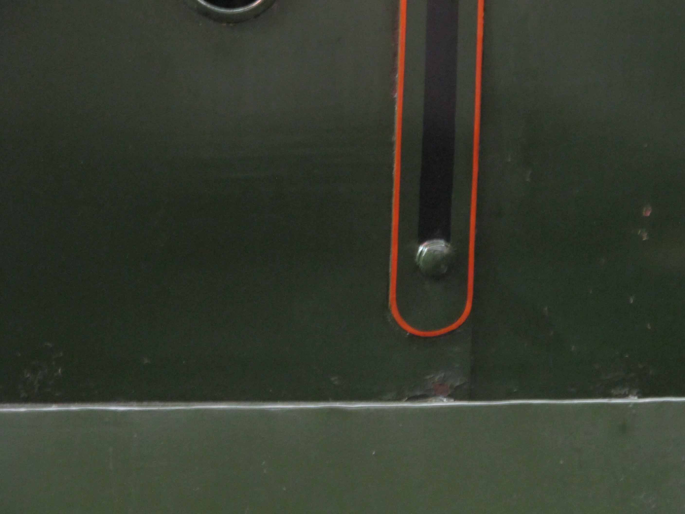
Boiler bands –
Lining Style 1. The bands were 2 ½” in width so there was a ⅛” Green edge to the band. Where the band was interrupted by clips the Orange line was closed off and the Black line stopped ½” short with a square end. On the fire box, only the sides were lined with the lining closed off at the edge of the top plate of the fire box. At the base the bands ended in a semicircle around the fixing rivet, here the Orange line also formed a semicircle and the Black line also had a square? end. See photo A10. Where the lining went under a cover it was not closed off.
Feed pipe cover plates (NOT Castles) –
The boiler feed pipes were positioned over a joint in the boiler cladding and were lined as a boiler band in Style 1 and closed off at the bottom with a straight Orange line. At the top the lining disappeared under the top feed cover plate.
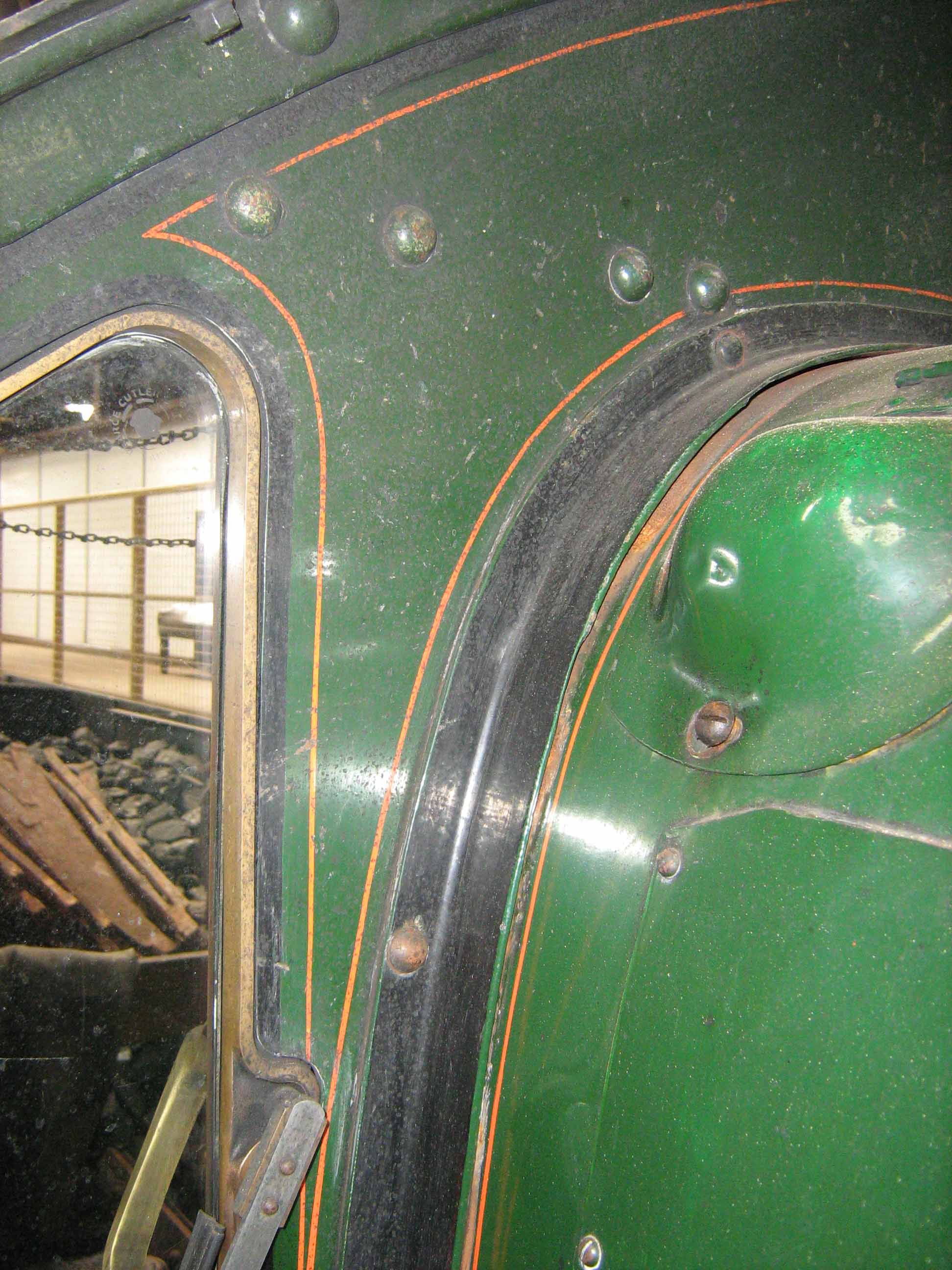
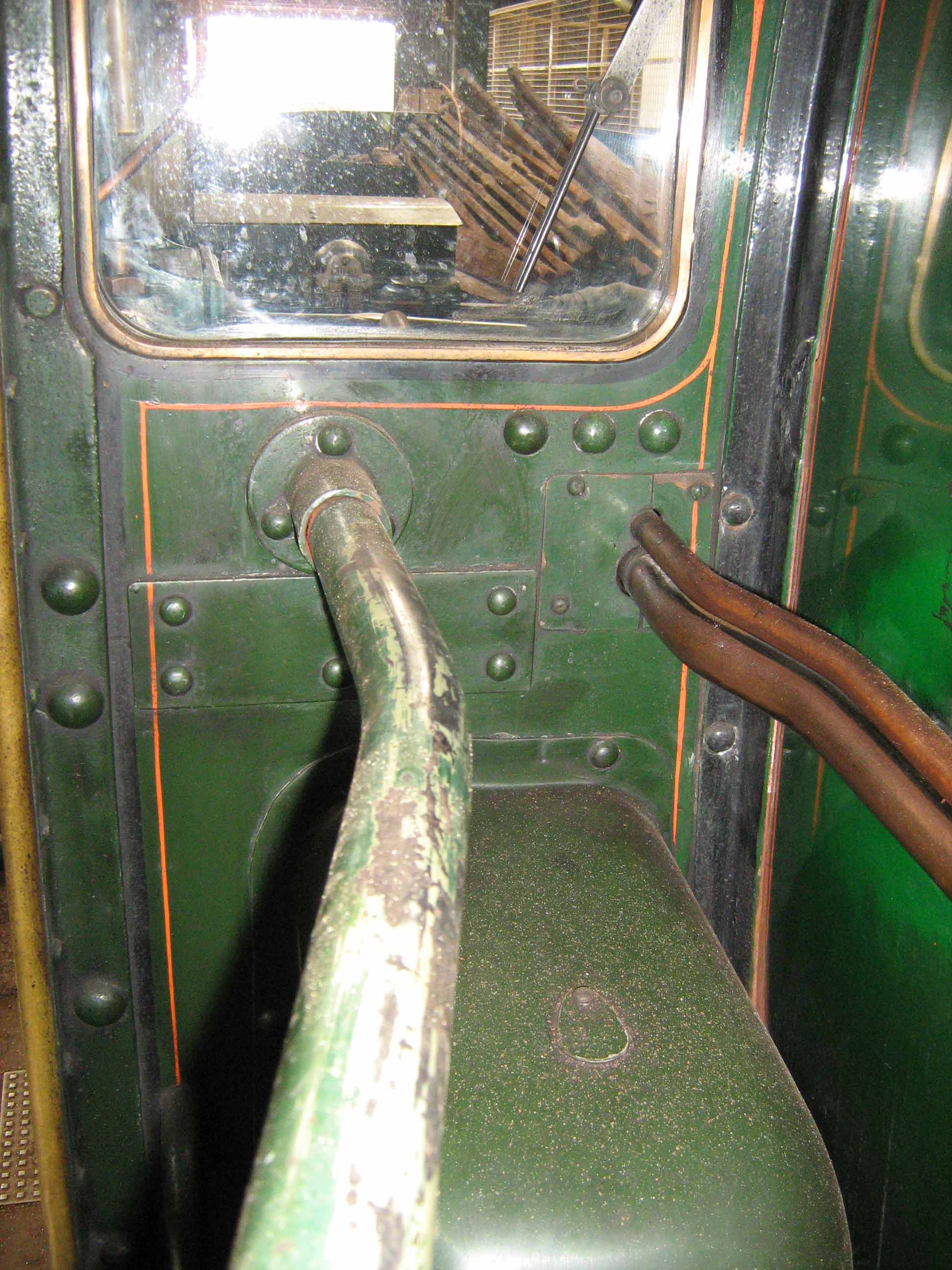
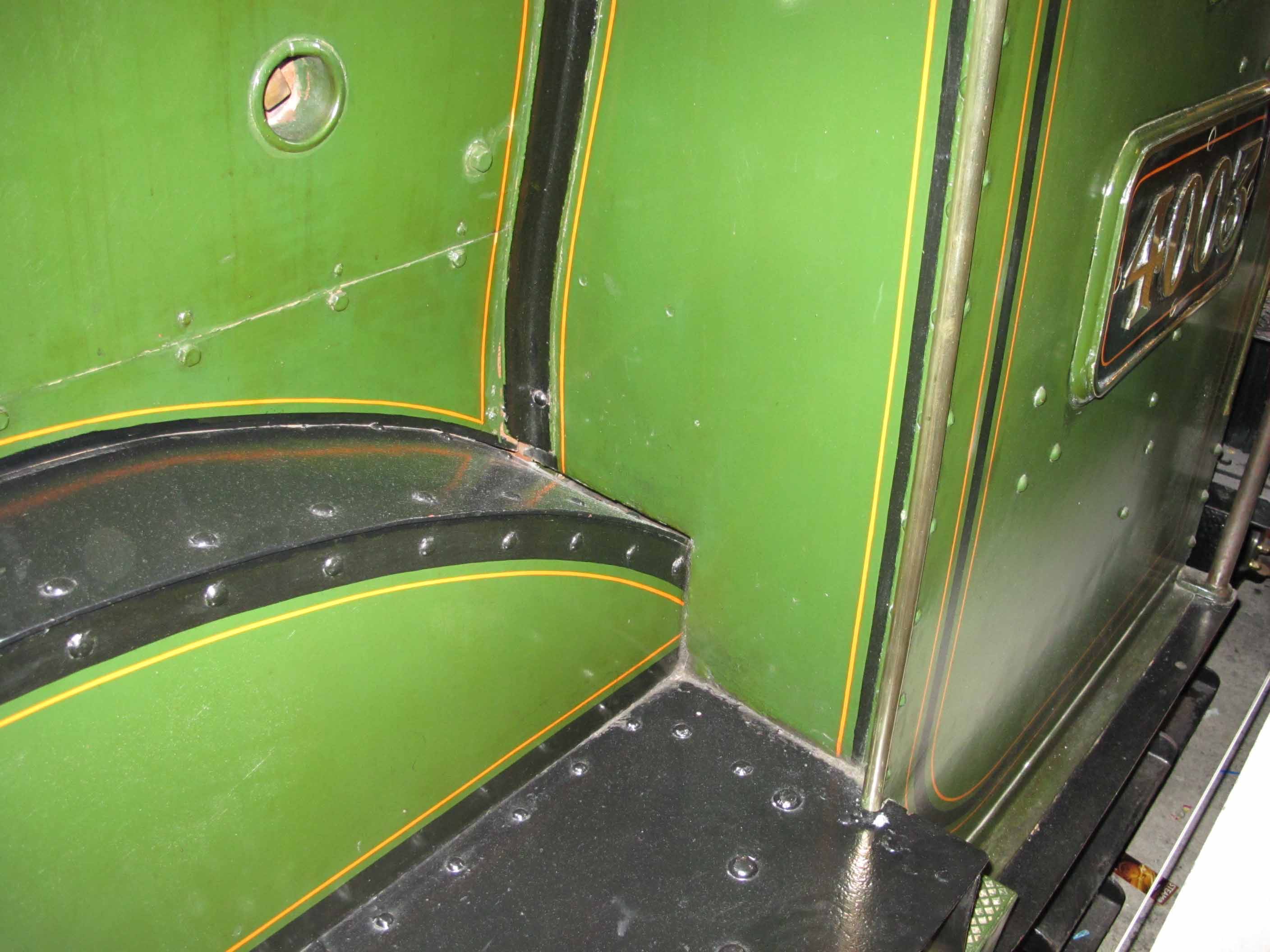
Within cab –
The rear edge of the cab sides within the cab were lined in Style 2. The edge is defined by the vertical brass beading and the inner edge of the angle forming the cut out beading. Where other stiffening plates and angles crossed the lining, the lining was omitted. See photos A14 & A15.
PHOTOGRAPHS OF LINING DETAILS ON GREEN AREAS (NOS. A1 - A16)
Lining on Black areas
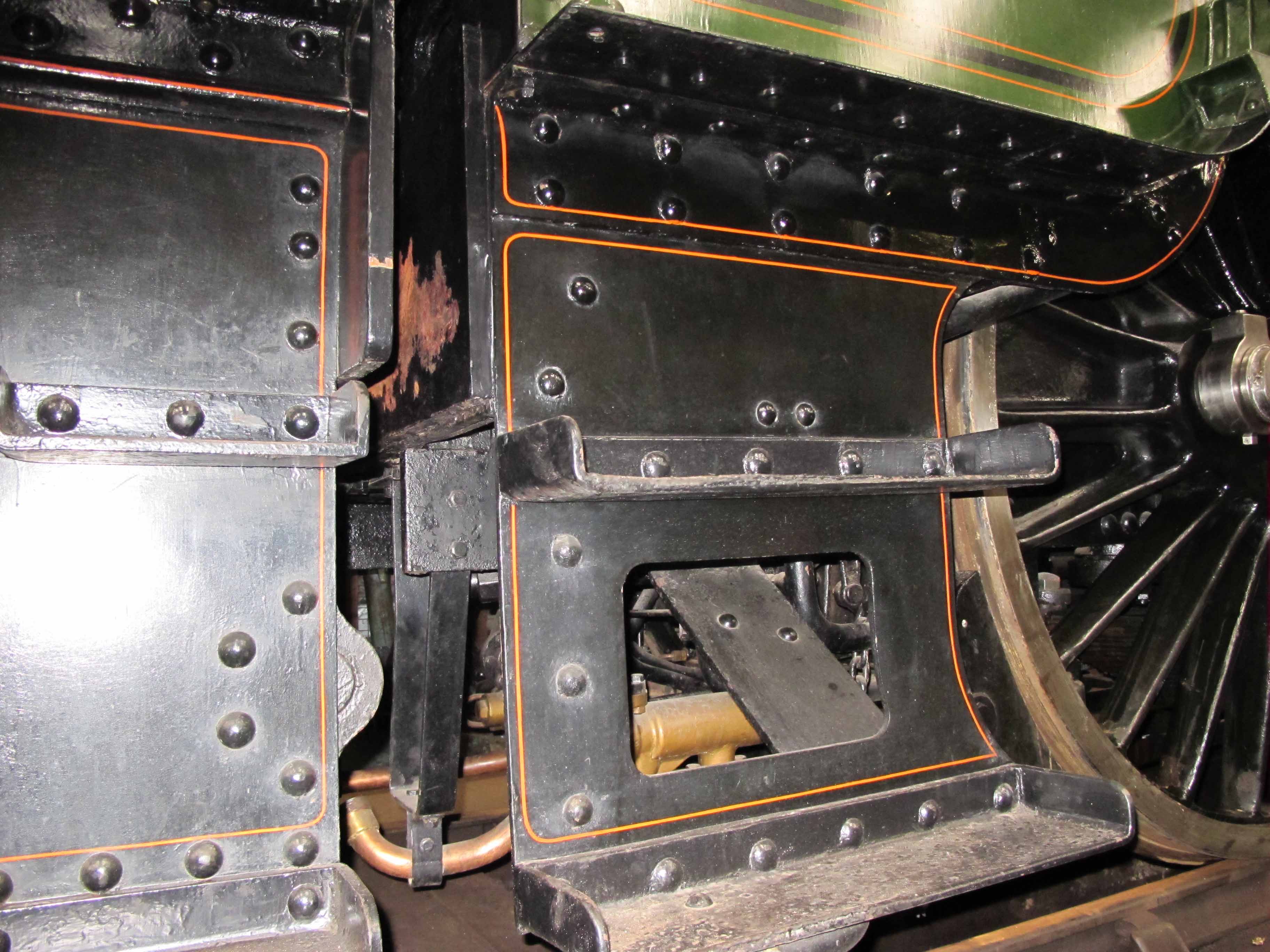
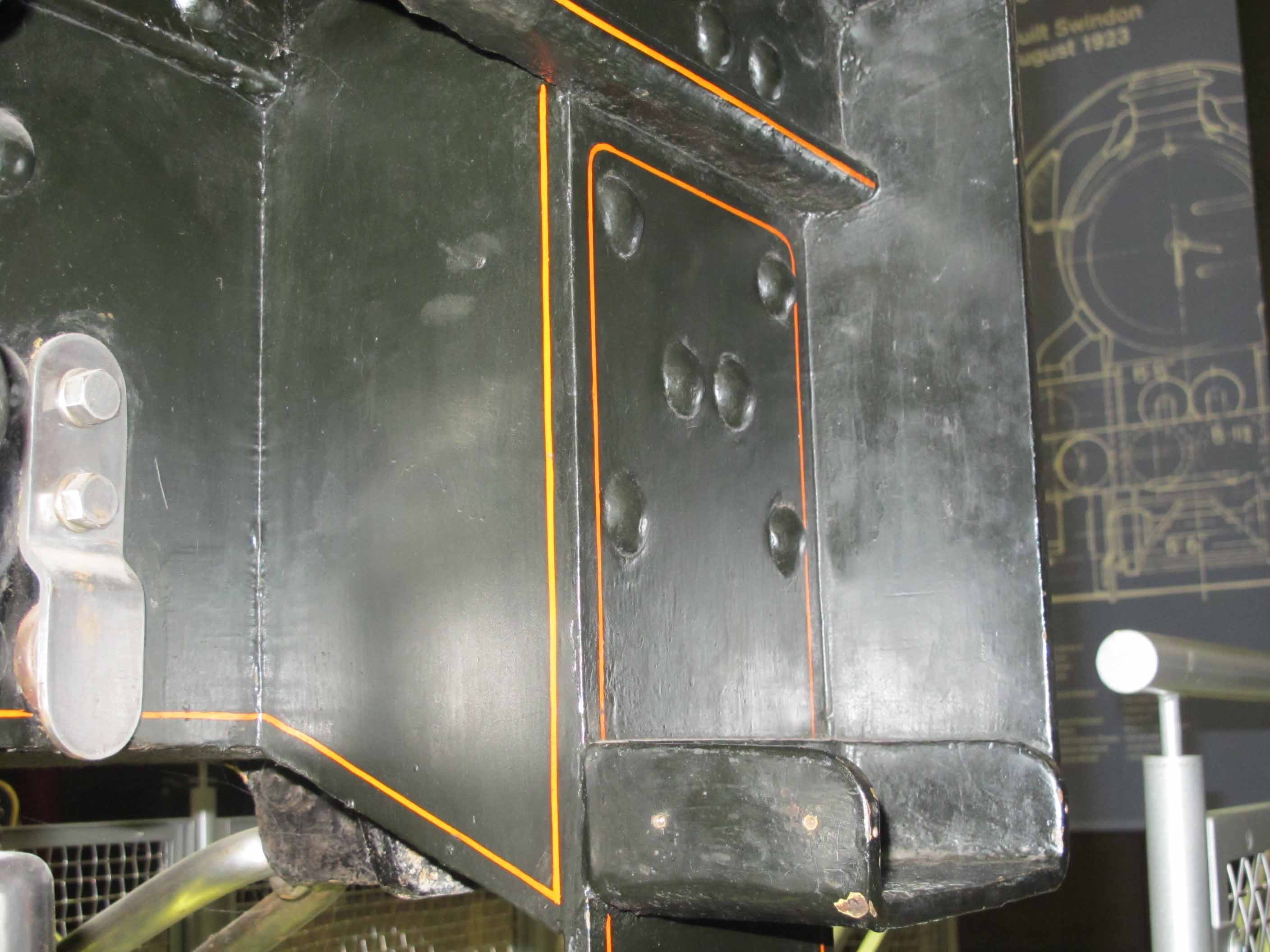
Hanging bars –
Lining Style 3 along bottom edge. At the ends of the hanging bar the lining turns up to finish at the underside of the running plate with a short curve into the corner. Right angle corners have a ½” radius but acute angles have no radius. At the front end the boundary of the hanging bar is the angle connecting the bar to the back of the buffer plate. The layout of the lining at the front end is best illustrated by a photograph but a description would be as follows. The lining at the front end of the hanging bar turns up and then curves into the top corner adjacent to the angle. The lining on the angle starts at top rear corner then curves out to drop vertically to the bottom corner where it turns along the bottom edge to the angle then it curves down into the very bottom corner. The lining on the other face of the angle starts from there, curves up in an S-bend until vertical then it finally curves into the top outer corner. See photo B1.
Tender hanging bars formed from bulb iron had the lining running along the centre of the 'bulb', see photo B6.
Step backing plates –
The lining, in Style 3, runs along the all edges except where broken by the upper step. The top edge is defined as the bottom of the hanging bar and the bottom edge is the top of the lower step angle. Right angle corners are rounded. See photo B2. The reinforcing angle behind the step plate on tenders was also lined, see photo B6.
Tender frames –
The lining, in Style 3, runs along the bottom edge but at each axle box guide the line scarfs into the edge.
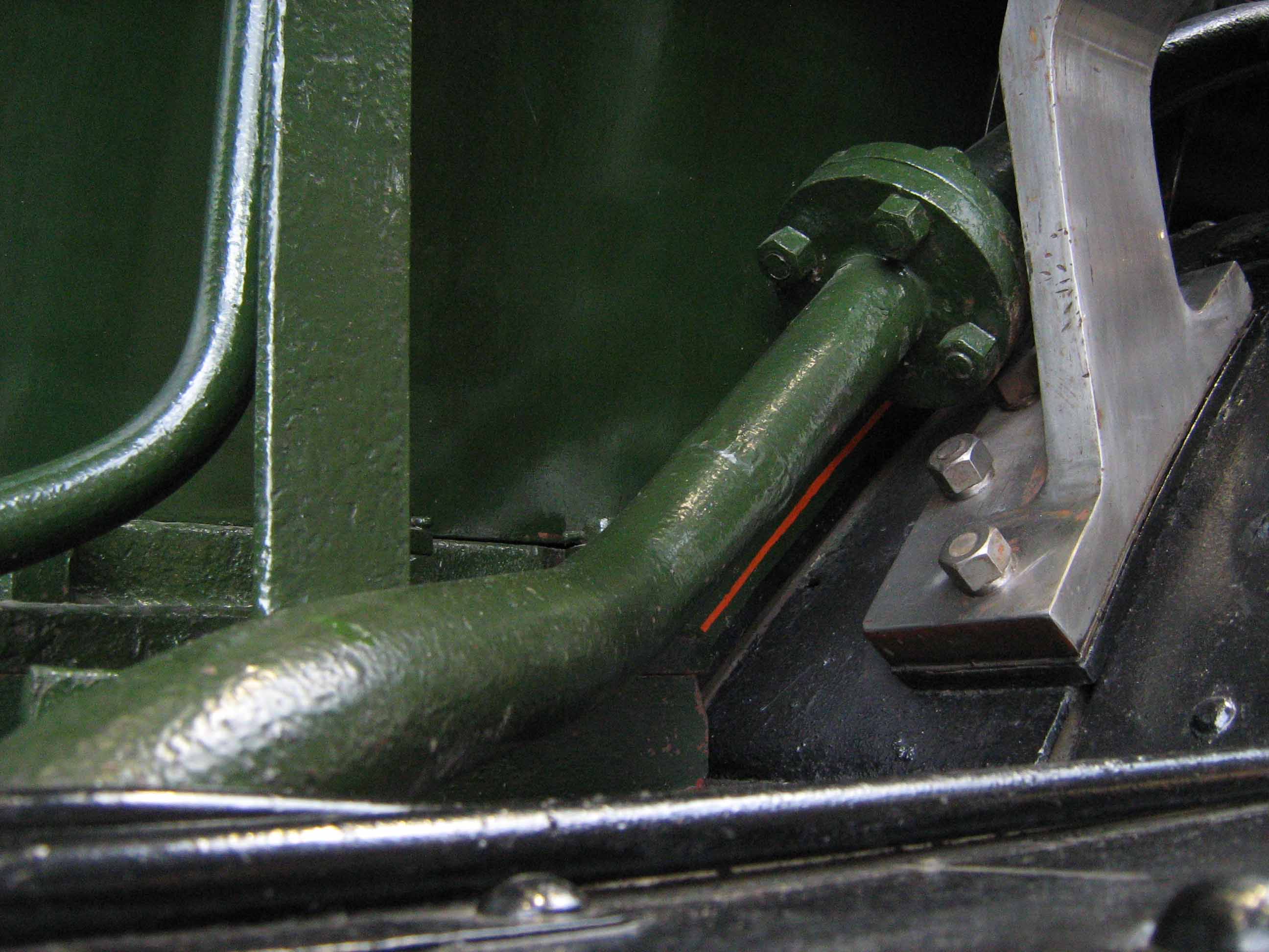
Outside cylinders –
Lining Style 5, basically as described above. The dimensions did vary slightly, particularly in the position of the lower edge of the panel. Generally, on 2 cylinder engines this was just above the level of the lower slide bar while on 4 cylinder engines it was approximately half way between piston rod and lower slide bar. A photograph showing the situation would be useful if painting a model. See photos B7, B8 & B9 for Castles and Kings
Bogie frames, King Class only –
Lining Style 3, top, bottom and front edge of the side frames and all edges of the front stretcher. The side frame lining runs as far back as the rear wheels and is not confined to just the outside frame portion ahead of the centre pivot.
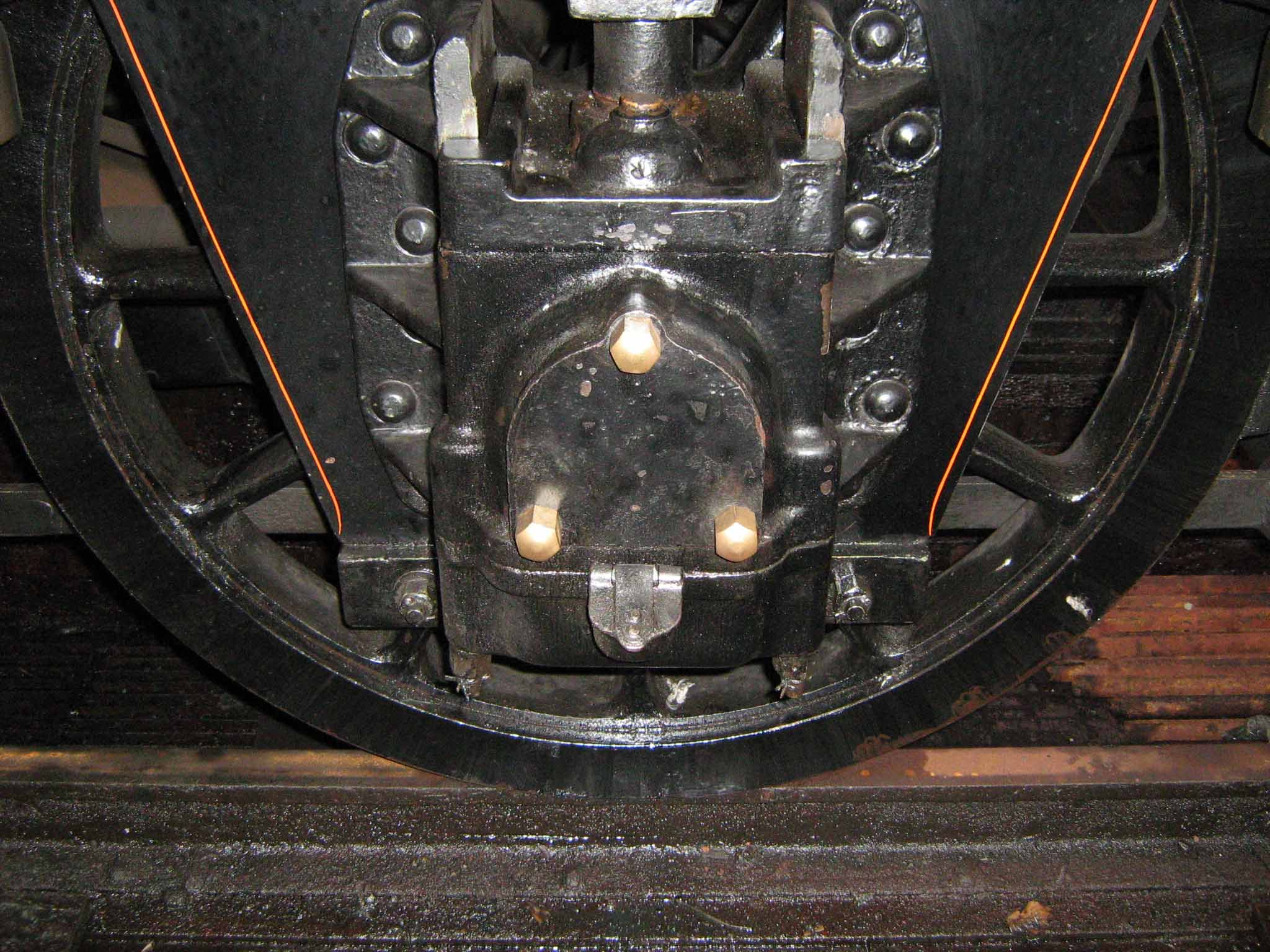
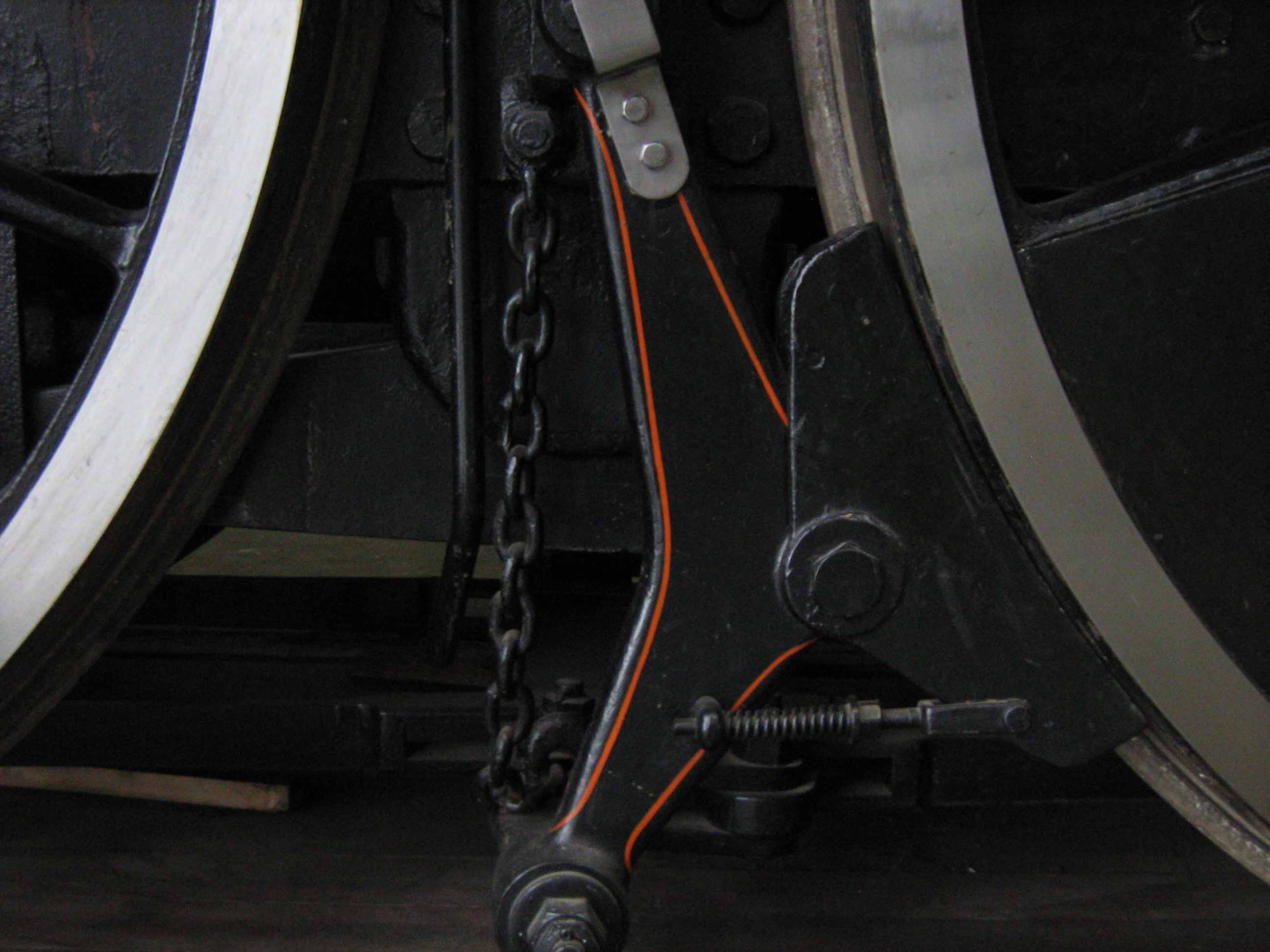
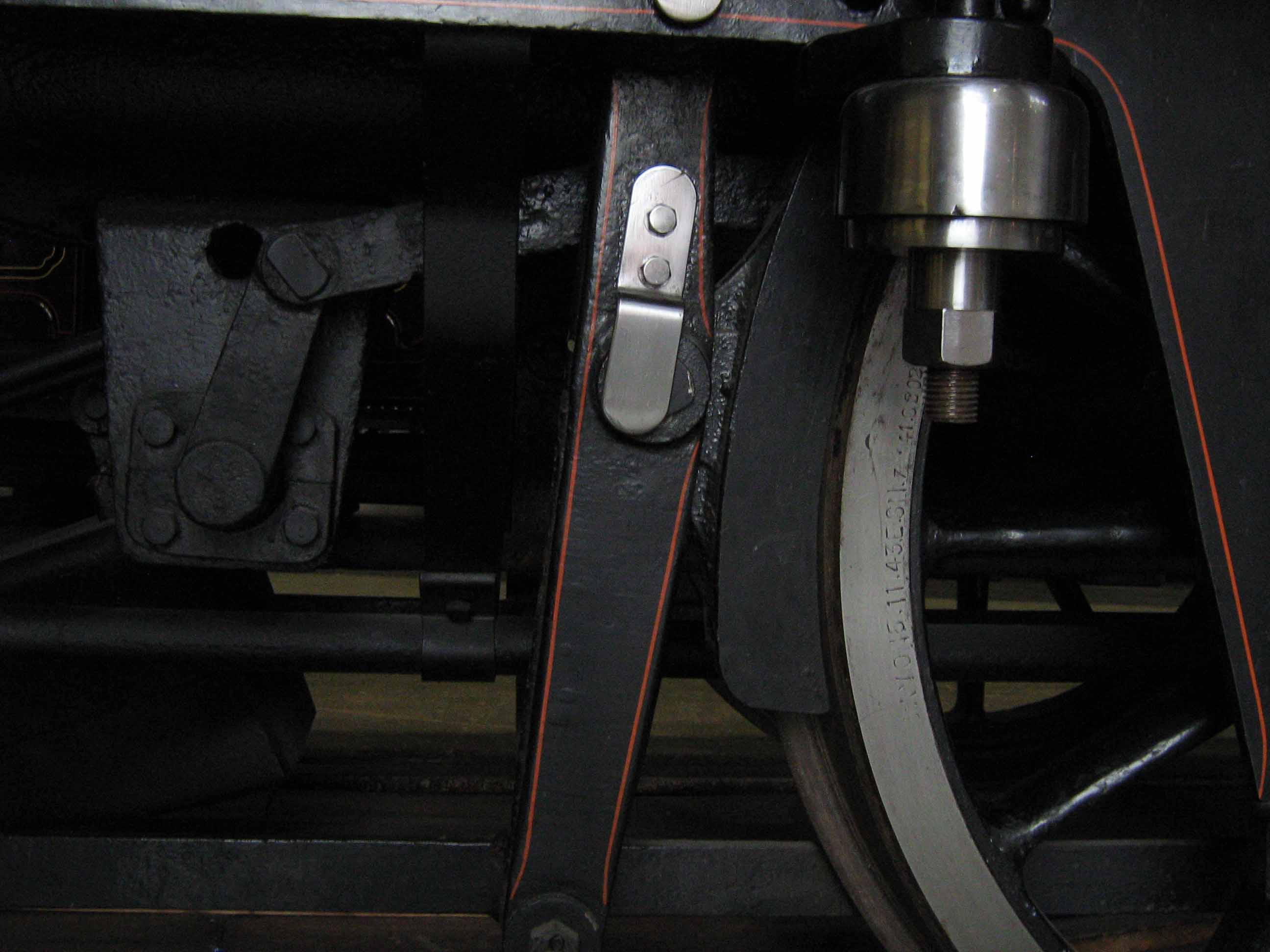
Brake hangers, engine and tender –
This lining is very difficult to see on photographs of engines in service, so did it exist? It can be seen on works grey photographs and it appears on the preserved ‘Lode Star’, which was painted at Swindon, on preservation, by people who had experience of the style in GWR days. The lining did not appear to be applied to ribbed hangers.
Lining style 3 on the front and back edges, scarfing into the edge top and bottom. See photos B4 and B5.
PHOTOGRAPHS OF LINING ON BLACK AREAS (NOS. B1 - B9)
Lining on China Red areas.
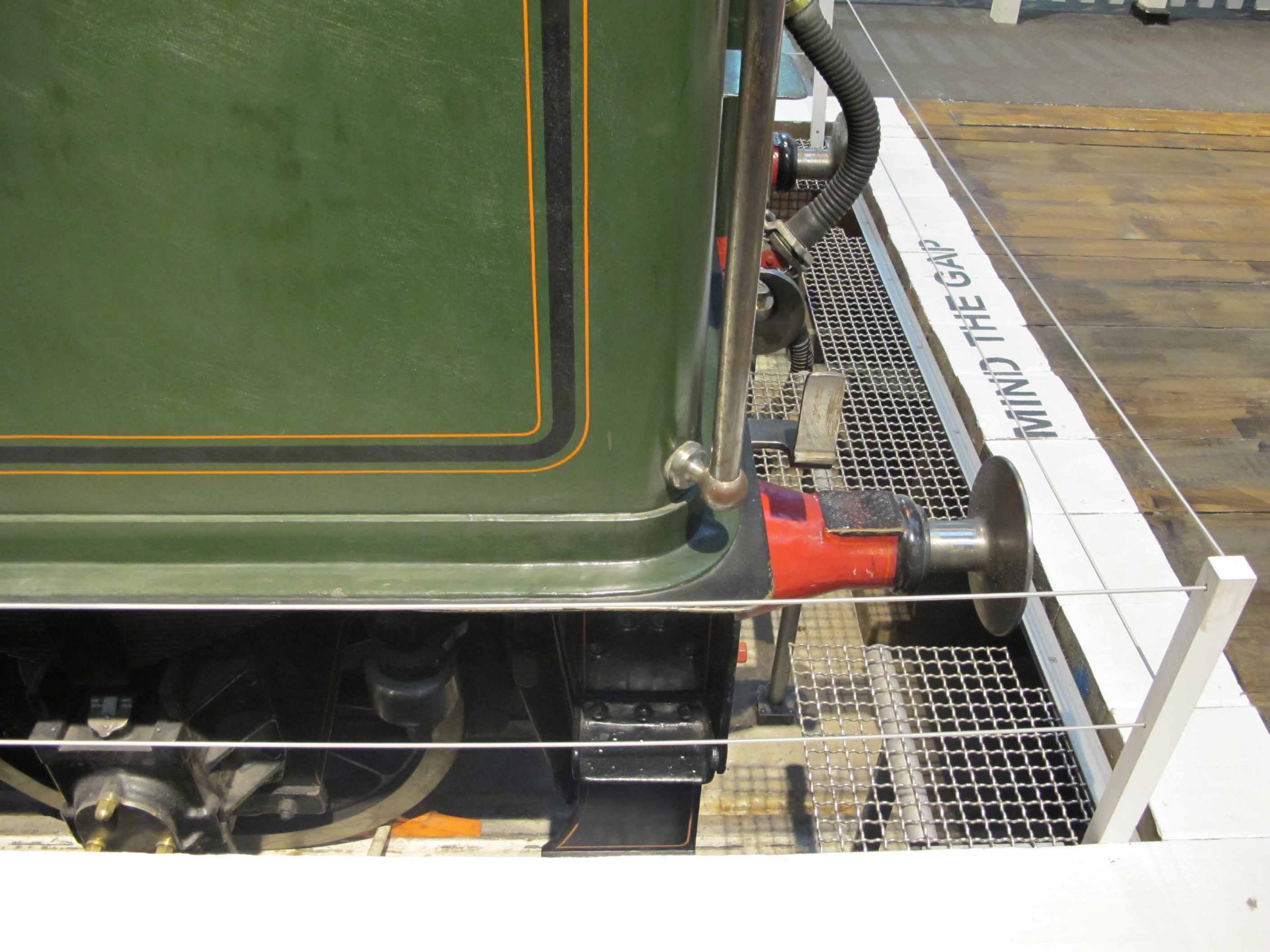
Locomotive buffer plate –
Lining Style 2 on top and bottom edges but due to Lining Rule 1 this changed to Style 3 on the side edges. The Black line followed a curve at the corners but disappeared at the ends. See photo C1.
Tender buffer plate –
Lining Style 2 on all edges. See photo C2
Buffer cases –
The rim and the step (and its sides) were painted Black. Lining Style 3 curving out from the back corner of the step and following the step and rim all the way round to end up on the other side of the step. See photo C3
PHOTOGRAPHS OF LINING ON RED AREAS (NOS. C1 - C4)
------------------------------------------------
Numbers and lettering.
Number plates –
The number plate was either brass or cast iron depending on the class of locomotive. On brass plates the numbers and rim were not painted. On cast iron plates the numbers and rim were picked out in pale Yellow. The back ground to the numbers was Black while outside the rim the plate was painted Green. In Livery Style A the background was lined in Style 3.
A list of which were brass or cast iron can be found on the links page.
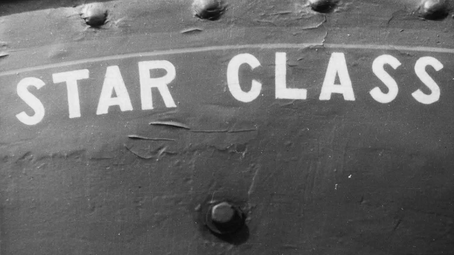
Stars with names removed -
The words 'Star Class' were painted in 2" white letters just below the lining on the splasher face. See photo D2 below.
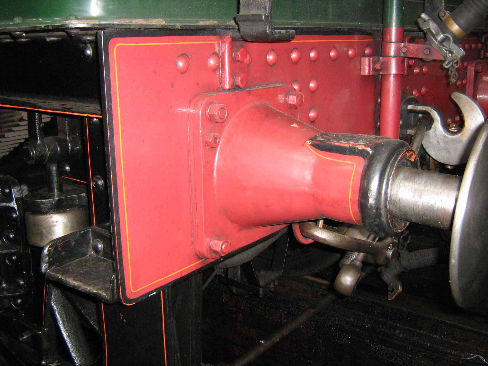
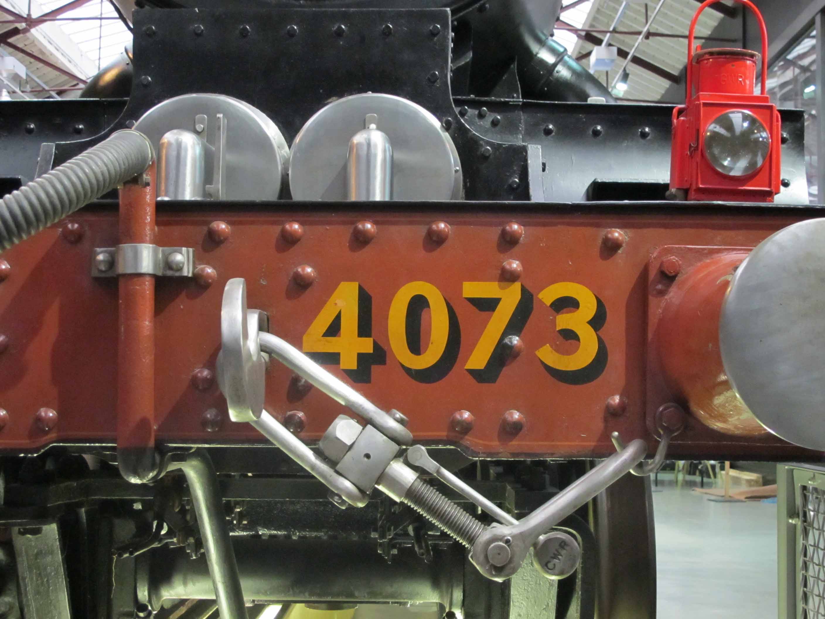
Buffer plate numbers –
On the front buffer plate and, on tank engines, the rear buffer plate, the numbers were put to the right of the coupling hook, centrally (the centre of the number and its shading) between hook and buffer case. The numbers were yellow, in a block style shaded to the right and below. See photo D1 below.
Route restriction disc –
The 4.5” diameter coloured disc for the route restriction was placed centrally above the number on engines with side window cabs. On other engines it was placed centrally on the upper cab side ahead of the cut out or on the shutter for engines so equipped. Check with a photograph for the exact position.
Power Class letter –
The letter A - E, in Black, was placed centrally within the restriction disc. Where there was no disc, on unrestricted engines, the letter was white, sometimes placed in a white circle, ie. not a disc.
Shed Code –
Shed codes on the hanging bar were introduced during the second world war. The normal place for the code for the engine’s home shed was the front end of the hanging bar before the drop to the buffer plate. The lettering was white block style generally 2” high but variable as it was done on shed and sometimes with stencils. Its location varied too, sometimes on a step plate, or other places at the front end of the hanging bar. Check with a photograph.
The shed code and the engine number were stencilled on the underside of the cab roof above the driver's head. Photo pending.
Tender number plates –
Tender number plates were painted Green, including the lettering, and placed just above the centre of the rear tender panel although the degree of variation on this is difficult to ascertain as photographs are so rare.
Great Western Identity –
At the Grouping some smaller GW engines carried no company lettering at all. These were generally saddle tanks confined to yards, and side tank engines with a number plate in the middle of the tanks, leaving no room for lettering. Unlike the other companies the GW used only one size of lettering and, if it didn’t fit, it was left off.
Absorbed engines were given GW number plates with the letters GWR above the number.
Engines in Livery Style A, until 1928, continued to carry the company coat of arms within a garter, between the words Great Western. On Collett tenders, left hand side, the garter was placed just in front of the central columns of rivets, and on the right, just behind the rivets. The lettering was set out so that the letters, in groups of one, two or three, lay between columns of rivets, with the spacing adjusted to suit. Between 1928 - 1934 (bearing in mind some engines carried the earlier style for some years until repainted) the garter coat of arms was replaced by the shields of London and Bristol, side by side. On other types of tender the position of the garter/shields was more fluid, so a check with a photo is essential.
Engines in Livery Style B, until late 1934 (again the style lasted longer on many engines) carried the words Great Western without any heraldic devices. On tenders the spacing was the same as in Style A but on tank engines it was affected by positioning of rivets and space available, so a check with photographs is essential. On some absorbed engines where the pattern of rivets did not suit the letter spacing some letters had to be positioned over a rivet. In this case the transfer was probably cut and the letter completed by hand painting.
In 1934 all elaborate lettering was swept away, by reason of economy and fashion, and replaced by the Art Deco monogram which lasted until the mid war years. On Collett tenders the monogram was placed on the central column of rivets, but a study of photographs shows that the lower two rivets appear to be flush with the surface to allow the transfer to sit flat. On flush sided tenders the monogram was positioned over the centre axle. For other rivetted tenders check with a photograph. On tanks it was affected by rivet positions so, again, check with a photo.
Engines in Livery Style C, Not known
Copyright Ian Rathbone MMXII